Stress concentration

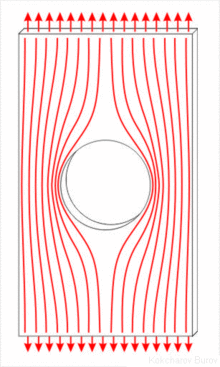
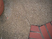
In solid mechanics, a stress concentration (also called a stress raiser or a stress riser or notch sensitivity) is a location in an object where the stress is significantly greater than the surrounding region. Stress concentrations occur when there are irregularities in the geometry or material of a structural component that cause an interruption to the flow of stress. This arises from such details as holes, grooves, notches and fillets. Stress concentrations may also occur from accidental damage such as nicks and scratches.
The degree of concentration of a discontinuity under typically tensile loads can be expressed as a non-dimensional stress concentration factor , which is the ratio of the highest stress to the nominal far field stress. For a circular hole in an infinite plate, .[1] The stress concentration factor should not be confused with the stress intensity factor, which is used to define the effect of a crack on the stresses in the region around a crack tip.[2]
For ductile materials, large loads can cause localised plastic deformation or yielding that will typically occur first at a stress concentration allowing a redistribution of stress and enabling the component to continue to carry load. Brittle materials will typically fail at the stress concentration. However, repeated low level loading may cause a fatigue crack to initiate and slowly grow at a stress concentration leading to the failure of even ductile materials. Fatigue cracks always start at stress raisers, so removing such defects increases the fatigue strength.
Description
[edit]Stress concentrations occur when there are irregularities in the geometry or material of a structural component that cause an interruption to the flow of stress.
Geometric discontinuities cause an object to experience a localised increase in stress. Examples of shapes that cause stress concentrations are sharp internal corners, holes, and sudden changes in the cross-sectional area of the object as well as unintentional damage such as nicks, scratches and cracks. High local stresses can cause objects to fail more quickly, so engineers typically design the geometry to minimize stress concentrations.
Material discontinuities, such as inclusions in metals, may also concentrate the stress. Inclusions on the surface of a component may be broken from machining during manufacture leading to microcracks that grow in service from cyclic loading. Internally, the failure of the interfaces around inclusions during loading may lead to static failure by microvoid coalescence.
Stress concentration factor
[edit]The stress concentration factor, , is the ratio of the highest stress to a nominal stress of the gross cross-section and defined as[3]
Note that the dimensionless stress concentration factor is a function of the geometry shape and independent of its size.[4] These factors can be found in typical engineering reference materials.

E. Kirsch derived the equations for the elastic stress distribution around a hole. The maximum stress felt near a hole or notch occurs in the area of lowest radius of curvature. In an elliptical hole of length and width , under a far-field stress , the stress at the ends of the major axes is given by Inglis' equation:[5]
where is the radius of curvature of the elliptical hole. For circular holes in an infinite plate where , the stress concentration factor is .
As the radius of curvature approaches zero, such as at the tip of a sharp crack, the maximum stress approaches infinity and a stress concentration factor cannot therefore be used for a crack. Instead, the stress intensity factor which defines the scaling of the stress field around a crack tip, is used.[2]
Causes of Stress Concentration
[edit]Stress concentration can arise due to various factors. The following are the main causes of stress concentration:
Material Defects: When designing mechanical components, it is generally presumed that the material used is consistent and homogeneous throughout. In practice, however, material inconsistencies such as internal cracks, blowholes, cavities in welds, air holes in metal parts, and non-metallic or foreign inclusions can occur. These defects act as discontinuities within the component, disrupting the uniform distribution of stress and thereby leading to stress concentration.
Contact Stress: Mechanical components are frequently subjected to forces that are concentrated at specific points or small areas. This localized application of force can result in disproportionately high pressures at these points, causing stress concentration. Typical instances include the interactions at the points of contact in meshing gear teeth,[6] the interfaces between cams and followers, and the contact zones in ball bearings.
Thermal Stress: Thermal stress occurs when different parts of a structure expand or contract at different rates due to variations in temperature. This differential in thermal expansion and contraction generates internal stresses, which can lead to areas of stress concentration within the structure.
Geometric Discontinuities: Features such as steps on a shaft, shoulders, and other abrupt changes in the cross-sectional area of components are often necessary for mounting elements like gears and bearings or for assembly considerations. While these features are essential for the functionality of the device, they introduce sharp transitions in geometry that become hotspots for stress concentration. Additionally, design elements like oil holes, grooves, keyways, splines, and screw threads also introduce discontinuities that further exacerbate stress concentration.
Rough Surface: Imperfections on the surface of components, such as machining scratches, stamp marks, or inspection marks, can interrupt the smooth flow of stress across the surface, leading to localized increases in stress. These imperfections, although often small, can significantly impact the durability and performance of mechanical components by initiating stress concentration.[7]
Methods for determining factors
[edit]There are experimental methods for measuring stress concentration factors including photoelastic stress analysis, thermoelastic stress analysis,[8] brittle coatings or strain gauges.
During the design phase, there are multiple approaches to estimating stress concentration factors. Several catalogs of stress concentration factors have been published.[9] Perhaps most famous is Stress Concentration Design Factors by Peterson, first published in 1953.[10][11] Finite element methods are commonly used in design today. Other methods include the boundary element method[12] and meshfree methods.
Limiting the effects of stress concentrations
[edit]Stress concentrations can be mitigated through techniques that smoothen the flow of stress around a discontinuity:
Material Removal: Introducing auxiliary holes in the high stress region to create a more gradual transition. The size and position of these holes must be optimized.[13][14] Known as crack tip blunting, a counter-intuitive example of reducing one of the worst types of stress concentrations, a crack, is to drill a large hole at the end of the crack. The drilled hole, with its relatively large size, serves to increase the effective crack tip radius and thus reduce the stress concentration.[4]
Hole Reinforcement: Adding higher strength material around the hole, usually in the form of bonded rings or doublers.[15] Composite reinforcements can reduce the SCF.
Shape Optimization: Adjusting the hole shape, often transitioning from circular to elliptical, to minimize stress gradients. This must be checked for feasibility. One example is adding a fillet to internal corners.[16] Another example is in a threaded component, where the force flow line is bent as it passes from shank portion to threaded portion; as a result, stress concentration takes place. To reduce this, a small undercut is made between the shank and threaded portions
Functionally Graded Materials: Using materials with properties that vary gradually can reduce the SCF compared to a sudden change in material.
The optimal mitigation technique depends on the specific geometry, loading scenario, and manufacturing constraints. In general, a combination of methods is required for the best result. While there is no universal solution, careful analysis of the stress flow and parameterization of the model can point designers toward an effective stress reduction strategy.
Examples
[edit]
- The de Havilland Comet aircraft experienced a number of catastrophic failures that were eventually found to be due to fatigue cracks growing from the high stress concentration caused by the use of punched rivet holes around the windows. The square passenger windows were also found to have higher stress concentrations than expected and were redesigned.
- Brittle fractures at the corners of hatches in Liberty ships in cold and stressful conditions in winter storms in the Atlantic Ocean.
- A focus point of stress on the margins of an implant, where metal meets bone, of an implanted orthosis is very likely to be the point of failure.
References
[edit]- ^ Todd, Greg. "Stress Concentrations at Holes". Fracture Mechanics.
- ^ a b Schijve, Jaap (2001). Fatigue of Structures and Materials. Springer. p. 90. ISBN 978-0792370147.
- ^ Shigley, Joseph Edward (1977). Mechanical Engineering Design (Third ed.). McGraw-Hill.
- ^ a b stress at round-tip notches an improved solution
- ^ "Stresses At Elliptical Holes". Retrieved 2020-03-13.
- ^ Tuplin WA. Gear-Tooth Stresses at High Speed. Proceedings of the Institution of Mechanical Engineers. 1950;163(1):162-175. doi:10.1243/PIME_PROC_1950_163_020_02
- ^ Persson, B.N.J. Surface Roughness-Induced Stress Concentration. Tribol Lett 71, 66 (2023). https://doi.org/10.1007/s11249-023-01741-4
- ^ Rajic, Nik; Street, Neil (2014). "A performance comparison between cooled and uncooled infrared detectors for thermoelastic stress analysis". Quantitative InfraRed Thermography Journal. 11 (2). Taylor & Francis: 207–221. doi:10.1080/17686733.2014.962835. S2CID 137607813.
- ^ ESDU64001: Guide to stress concentration data. ESDU. ISBN 1-86246-279-8.
- ^ Peterson, Rudolf Earl (1953). Stress Concentration Design Factors. John Wiley & Sons. ISBN 978-0471683766.
- ^ Pilkey, Walter D. (1999). Peterson's Stress Concentration Factors (2nd ed.). Wiley. ISBN 0-471-53849-3.
- ^ R. T. Fenner, “The boundary integral equation and boundary element method in engineering stress analysis”, The Journal of Strain Analysis for Engineering Design IMechE, vol. 18, no. 4, pp. 199-205, 1983.
- ^ K. Rajaiah and A. J. Durelli, “Optimum hole shapes in finite plates under uni-axial load,” Applied Mechanics, vol. 46(3), pp. 691-695, 1979.
- ^ S. A. Meguid, “Finite element analysis of defence hole systems for the reduction of stress Concentration in a uniaxially–loaded plate with coaxial holes,” Engineering Fracture Mechanics, vol. 25, no. 4, pp. 403-413, 1986.
- ^ G. S. Giare and R. Shabahang, “The reduction of stress concentration around the hole in an isotropic plate using composite material,” Engineering Fracture Mechanics, vol. 32, no. 5, pp. 757-766, 1989.
- ^ Z. Wu, “Optimal hole shape for minimum stress concentration using parameterized geometry models,” Structural and Multidisciplinary Optimization, vol. 37, no. 6, pp. 625-634, Feb, 2009.


